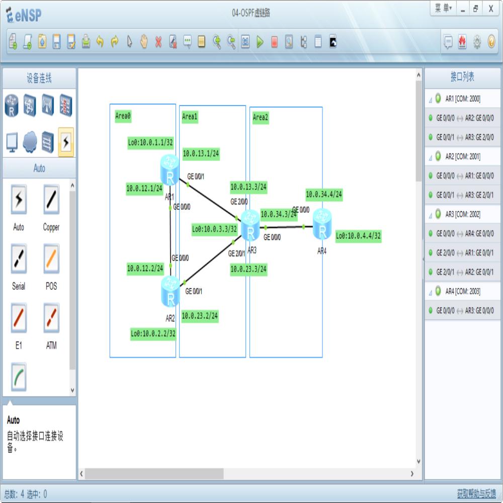
OSPF虚链路解决非直连区域以及解决Area0被分割
首先静态IP,并且宣告到OSPF进程中,注意宣告到不同区域;
[AR1]
router id 10.0.1.1
interface GigabitEthernet0/0/0
ip address 10.0.12.1 255.255.255.0
interface GigabitEthernet0/0/1
ip address 10.0.13.1 255.255.255.0
interface LoopBack0
ip address 10.0.1.1 255.255.255.255
ospf 1
area 0.0.0.0
network 10.0.1.1 0.0.0.0
network 10.0.12.1 0.0.0.0
area 0.0.0.1
network 10.0.13.1 0.0.0.0
[AR2]
router id 10.0.2.2
interface GigabitEthernet0/0/0
ip address 10.0.12.2 255.255.255.0
interface GigabitEthernet0/0/1
ip address 10.0.23.2 255.255.255.0
interface LoopBack0
ip address 10.0.2.2 255.255.255.255
ospf 1
area 0.0.0.0
network 10.0.2.2 0.0.0.0
network 10.0.12.2 0.0.0.0
area 0.0.0.1
network 10.0.23.2 0.0.0.0
[AR3]
router id 10.0.3.3
interface GigabitEthernet0/0/0
ip address 10.0.34.3 255.255.255.0
interface GigabitEthernet2/0/0
ip address 10.0.13.3 255.255.255.0
interface GigabitEthernet2/0/1
ip address 10.0.23.3 255.255.255.0
interface LoopBack0
ip address 10.0.3.3 255.255.255.255
ospf 1
area 0.0.0.1
network 10.0.3.3 0.0.0.0
network 10.0.13.3 0.0.0.0
network 10.0.23.3 0.0.0.0
area 0.0.0.2
network 10.0.34.3 0.0.0.0
[AR4]
router id 10.0.4.4
interface GigabitEthernet0/0/0
ip address 10.0.34.4 255.255.255.0
interface LoopBack0
ip address 10.0.4.4 255.255.255.255
ospf 1
area 0.0.0.2
network 10.0.4.4 0.0.0.0
network 10.0.34.4 0.0.0.0
查看AR3上午OSPF邻居关系,可以看到AR3的邻居关系都是Full状态;
<AR3>display ospf peer bri
OSPF Process 1 with Router ID 10.0.3.3
Peer Statistic Information
----------------------------------------------------------------------------
Area
Id Interface Neighbor id State
0.0.0.1 GigabitEthernet2/0/0 10.0.1.1 Full
0.0.0.1 GigabitEthernet2/0/1 10.0.2.2 Full
0.0.0.2 GigabitEthernet0/0/0 10.0.4.4 Full
----------------------------------------------------------------------------
查看AR4的LSDB,发现没有关于Area0中的10.0.1.1/32和10.0.2.2/32的LSA,也没有任何其他Area的LSA,仅仅只有本区域的Type1 LSA和Type2 LSA,因为Area2并未与Area0直连;
所以需要使用虚链路使得Area2与Area0在逻辑上互相连接起来;
在AR3和AR1上进行配置;
[AR3]ospf 1
[AR3-ospf-1]area 1
[AR3-ospf-1-area-0.0.0.1]vlink-peer 10.0.1.1
[AR1]ospf 1
[AR1-ospf-1]area 1
[AR1-ospf-1-area-0.0.0.1]vlink-peer 10.0.3.3
之后再AR1上查看虚链路的状态,发现已经建立了虚连接,并且Full状态;
[AR1]display ospf vlink
OSPF Process 1 with Router ID 10.0.1.1
Virtual Links
Virtual-link Neighbor-id -> 10.0.3.3, Neighbor-State: Full
Interface: 10.0.13.1 (GigabitEthernet0/0/1)
Cost: 1
State: P-2-P Type: Virtual
Transit
Area: 0.0.0.1
Timers: Hello 10 , Dead 40 , Retransmit 5 ,
Transmit Delay 1
GR
State: Normal
之后在AR4上查看LSDB,出现了AR3通告的Type3类LSA;
<AR4>display ospf lsdb
OSPF Process 1 with Router ID 10.0.4.4
Link State Database
Area: 0.0.0.2
Type
LinkState ID AdvRouter Age
Len Sequence Metric
Router
10.0.3.3 10.0.3.3 174
36 80000006 1
Router
10.0.4.4 10.0.4.4 1521
48 80000005 0
Network
10.0.34.3 10.0.3.3 1517
32 80000002 0
Sum-Net
10.0.13.0 10.0.3.3 174
28 80000001 1
Sum-Net
10.0.12.0 10.0.3.3 174
28 80000001 2
Sum-Net
10.0.3.3 10.0.3.3 174
28 80000001 0
Sum-Net
10.0.2.2 10.0.3.3 174
28 80000001 1
Sum-Net
10.0.1.1 10.0.3.3 174
28 80000001 1
Sum-Net
10.0.23.0 10.0.3.3 174
28 80000001 1
同样也可以在AR3和AR2之间建立虚链路;
[AR3-ospf-1-area-0.0.0.1]vlink-peer 10.0.2.2
[AR2-ospf-1-area-0.0.0.1]vlink-peer 10.0.3.3
之后在AR3上查看虚链路的状态,可以看到两条等价的虚链路,cost均为1;
[AR3-ospf-1]display ospf vlink
OSPF Process 1 with Router ID 10.0.3.3
Virtual Links
Virtual-link Neighbor-id -> 10.0.1.1, Neighbor-State: Full
Interface: 10.0.13.3 (GigabitEthernet2/0/0)
Cost: 1
State: P-2-P Type: Virtual
Transit Area: 0.0.0.1
Timers: Hello 10 , Dead 40 , Retransmit 5 ,
Transmit Delay 1
GR
State: Normal
Virtual Links
Virtual-link Neighbor-id -> 10.0.2.2, Neighbor-State: Full
Interface: 10.0.23.3 (GigabitEthernet2/0/1)
Cost: 1
State: P-2-P Type: Virtual
Transit Area: 0.0.0.1
Timers: Hello 10 , Dead 40 , Retransmit 5 ,
Transmit Delay 1
GR
State: Normal
可以修改虚链路的接口开销值,形成一条备用链路;
在AR3的G2/0/1和AR2的G0/0/1上,修改cost值为10;
[AR3]int g 2/0/1
[AR3-GigabitEthernet2/0/1]ospf cost 10
[AR2]int g 0/0/1
[AR2-GigabitEthernet0/0/1]ospf cost 10
之后可以看到,AR3到AR2的虚链路的cost值变为了10;
[AR3]display ospf vlink
OSPF Process 1 with Router ID 10.0.3.3
Virtual Links
Virtual-link Neighbor-id -> 10.0.1.1, Neighbor-State: Full
Interface: 10.0.13.3 (GigabitEthernet2/0/0)
Cost: 1
State: P-2-P Type: Virtual
Transit Area: 0.0.0.1
Timers: Hello 10 , Dead 40 , Retransmit 5 ,
Transmit Delay 1
GR
State: Normal
Virtual Links
Virtual-link Neighbor-id -> 10.0.2.2, Neighbor-State: Full
Interface: 10.0.23.3 (GigabitEthernet2/0/1)
Cost: 10
State: P-2-P Type: Virtual
Transit Area: 0.0.0.1
Timers: Hello 10 , Dead 40 , Retransmit 5 ,
Transmit Delay 1
GR
State: Normal
虚链路还能作为Area0中的链路的冗余备份;
AR1和AR2之间只有单条链路,一旦出现故障,就会导致Area0被分割,所以可以以Area1位传输区域,在AR1和AR2之间建立一条虚链路作为冗余备份;
[AR1]ospf 1
[AR1-ospf-1]area 1
[AR1-ospf-1-area-0.0.0.1]vlink-peer 10.0.2.2
[AR2]ospf 1
[AR2-ospf-1]area 1
[AR2-ospf-1-area-0.0.0.1]vlink-peer 10.0.1.1
之后在AR1上查看虚链路的信息,可以看到AR1和AR2之间的虚链路的cost是11;
[AR1]display ospf vlink
OSPF Process 1 with Router ID 10.0.1.1
Virtual Links
Virtual-link Neighbor-id -> 10.0.2.2, Neighbor-State: Full
Interface: 10.0.13.1 (GigabitEthernet0/0/1)
Cost: 11
State: P-2-P Type: Virtual
Transit Area: 0.0.0.1
Timers:
Hello 10 , Dead 40 , Retransmit 5 , Transmit Delay 1
GR
State: Normal
Virtual Links
Virtual-link Neighbor-id -> 10.0.3.3, Neighbor-State: Full
Interface: 10.0.13.1 (GigabitEthernet0/0/1)
Cost: 1
State: P-2-P Type: Virtual
Transit Area: 0.0.0.1
Timers: Hello 10 , Dead 40 , Retransmit 5 ,
Transmit Delay 1
GR
State: Normal
在AR1上使用tracert测试,目前AR1和AR2之间是使用直连链路进行通讯的;
[AR1]tracert 10.0.2.2
traceroute to
10.0.2.2(10.0.2.2), max hops: 30 ,packet length: 40,press CTRL_C to
break
1
10.0.12.2 40 ms 30 ms 10 ms
关闭AR1的G0/0/0,模拟链路故障;
[AR1]int g 0/0/0
[AR1-GigabitEthernet0/0/0]shutdown
再次tracert,可以看到使用了虚链路进行通讯,经过了AR3;
[AR1]tracert 10.0.2.2
traceroute to
10.0.2.2(10.0.2.2), max hops: 30 ,packet length: 40,press CTRL_C to
break
1
10.0.13.3 30 ms 20 ms 30 ms
2
10.0.23.2 30 ms 20 ms 20 ms
王亦军 老师 上海腾科
2018.03.23 提交上传


